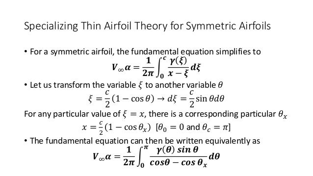

The equation is summed along the chord line to find initially coefficient A 0. The solution is based on Glauert's integral method. The solution for coefficients ( A 0,A 1,A 2.) can now be obtained from this equation. Substituting this result for induced velocity into the boundary condition equation gives Where x is the location at which the induced velocity is being calculated and s is the chordwise location of the vortex element. The velocity induced vertically ( v i) at any point on the mean line can be found by summing up the effects of small individual segments ( ds) of the vorticity distribution.

If small angle assumptions are made for the incidence, the boundary condition equation becomes Where u i and v i are the horizontal and vertical velocities induced by the vortex distribution.īoth of these components will be much less than the freestream velocity so for small angles of incidence the horizontal vortex induced component can be neglected. The flow horizontal and vertical velocities are made up of freestream and vortex induced components. The ratio of vertical to horizontal velocity at the surface must equal the surface (mean line) gradient. This condition can be formulated in terms of horizontal and vertical flow velocity components. Given an aerofoil geometry, freestream velocity and angle of incidence, the magnitude of the coefficients ( A 0,A 1,A 2.) is to be found by solving the condition of zero flow normal to the surface. Finally, both parts are scaled by multiplying by the freestream velocity.
THIN AIRFOIL THEORY ASSUMPTIONS SERIES
The second part is a Fourier sine series which will account for variation due to camber. The first is a constant coefficient ( A o) multiplied by a tangent function which describes the variation due to angle of incidence effects. The vorticity distribution function has two parts.

For these thin cambered plate models a boundary condition of zero flow normal to the surface is applied in order to create an equation that can be solved for the required strengths. The magnitude of the vortex distribution strength must be calculated to complete the mathematical model. For typical aerofoils with small camber, the difference is negligible. Note that chordwise position ( x) is used instead of distance along the mean line ( s). ) which is related to chordwise position ( x) as follows, The vorticity distribution is given as a function of the angular variable ( q This function is Glauert's approximation and is based on Joukowski transformation results and obeys the Kutta condition with zero vorticity at the trailing edge. The assumed distribution function is shown in the following equation. The vortices along the mean line form a continuous vorticity distribution. For incompressible, inviscid flow, an aerofoil section can be modelled by a distribution of vortices along the mean line. A simple solution for general two-dimensional aerofoil sections can be obtained by neglecting thickness effects and using a mean-line only section model.


 0 kommentar(er)
